Introduction
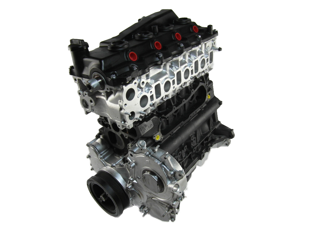
Toyota’s 2AD-FTV was a 2.2-litre four-cylinder turbo-diesel engine. Key features of the 2AD-FTV engine included its aluminium alloy block and cylinder head, double overhead camshafts (chain and gear-driven) and four valves per cylinder. While the 2AD-FTV engine initially had solenoid injectors, piezo injectors were introduced in 2008.
For Australia, the 2AD-FTV engine has only been offered in the Toyota XA40 RAV4.
| Engine | Trans. | Years | Peak power | Peak torque | |
|---|---|---|---|---|---|
| ToyotaXA40 RAV4 | 2.2-litre turbo-diesel I4 | 6sp man., 6sp auto |
2013-on | 110kW at 3600rpm | 340Nm at 2000-2800rpm |
2AD-FTV block
The 2AD-FTV engine had an aluminium alloy cylinder block with 86.0 mm bores and a 96.0 mm stroke for a capacity of 2231 cc. Within the bores, the 2AD-FTV engine had ‘spiny type’ cylinder liners that were manufactured so that their casting exteriors formed large irregular surfaces to improve adhesion between the liners and the cylinder block – this improved heat dissipation and reduced heat deformation of the cylinder bores. To keep the temperature of the cylinder walls uniform, the 2AD-FTV cylinder block had coolant passages between the bores.
Crankshaft, connecting rods and pistons
The forged steel crankshaft for the 2AD-FTV engine had five journals, four connecting rod pins, seven counter weights and a balance shaft drive gear. To reduce noise and increase coupling rigidity with the crankshaft, the 2AD-FTV engine had crankshaft bearing caps within the lower cylinder block case and plastic region tightening bolts were used. Furthermore, part of the bearing journal of the crankshaft bearing cap was produced from cast iron to prevent deformation under load from the crankshaft. For quieter running, the crankshaft pulley had a built-in torsional damper.
The connecting rods and caps for the 2AD-FTV engine were made from high-strength steel. To minimise the shifting of the bearing caps during assembly, knock pins were used at the matching surfaces of the bearing caps of the connecting rod. To reduce mass, the connecting rods had nutless-type plastic region tightening bolts.
For the aluminium alloy pistons, the top of the piston was shaped for a low compression ratio, high engine output and low fuel consumption. Attributes of the pistons included:
- Full floating-type piston pins;
- A resin coating for the piston skirts to reduce frictional losses;
- An Ni-resist cast iron ring carrier to improve wear resistance for the top piston ring groove; and,
- A cooling channel to improve cooling.
Balance shaft
The 2AD-FTV had twin counter-rotating balance shafts within the crankcase to cancel the secondary inertia forces that were inherent in an in-line four-cylinder engine. Since each piston reached its maximum speed – both rising and falling – at a point just above the centre of the stroke, the upward inertial force of the two rising pistons was greater than the downward inertial force of the two falling pistons. To offset this, the twin gear-driven balance shafts counter-rotated at twice the speed of the crankshaft.
For the 2AD-FTV engine, the no.1 balance shaft was driven by the crankshaft via a scissors gear, while the no.2 balance shaft was driven by the no.1 balance shaft.
Intercooler and throttle
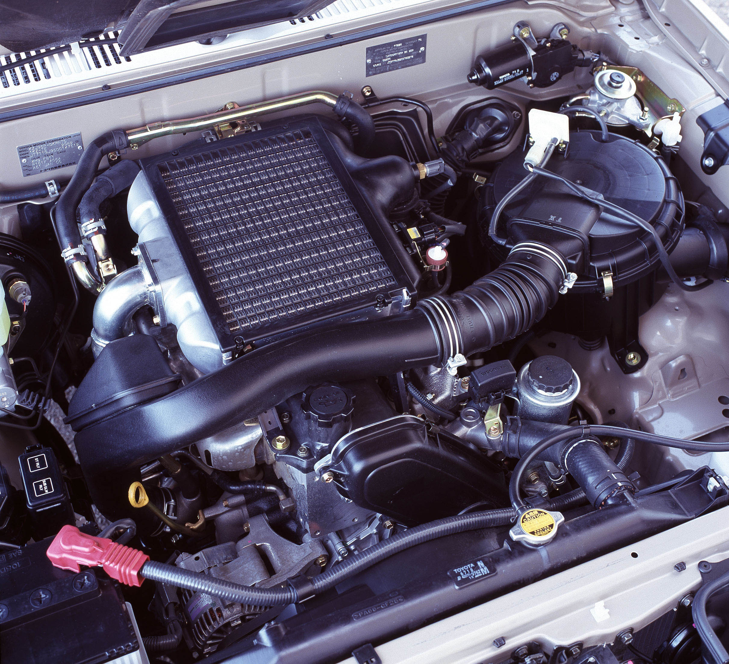
The 2AD-FTV engine had an air-cooled intercooler to lower intake air temperature. Furthermore, the 2AD-FTV engine had a linkless-type throttle body which integrated the throttle motor – which used a rotary solenoid motor – and contactless throttle position sensor.
Turbocharger
The 2AD-FTV engine had an oil-cooled, variable nozzle vane type turbocharger. Exhaust gas from the exhaust manifold passed through the nozzle vane inside the turbocharger housing and then flowed to the exhaust pipe through the turbine wheel. The speed of the turbine wheel (and hence turbocharging pressure) varied according to the opening of the nozzle valve. For example,
- At idle, exhaust gas flow was relatively low and the nozzle vane was fully closed. However, since there was a slight clearance between the vanes, exhaust gas would flow through this clearance to the exhaust pipe (i.e. no bypass);
- At low engine loads or speeds, the nozzle vane actuator would retract the actuator linkage which was connected to a unison ring – this would cause the drive arms on the unison ring to change nozzle vane angle toward the closed position. As a result, the flow velocity of the exhaust gas to the turbocharger increased for greater torque output; and,
- At high engine loads or speeds, the actuator would pull down the actuator linkage and the drive arms would change nozzle vane angle toward the open position – this would maintain the specified turbocharging pressure and reduce exhaust gas back pressure, improving power output and fuel consumption.
Cylinder head
The 2AD-FTV engine had an aluminium alloy cylinder head which included a water jacket that surrounded the intake and exhaust ports for cooling. Furthermore, the aluminium cylinder head cover was mounted on an acrylic rubber gasket.
Double overhead camshafts (DOHC)
For the 2AD-FTV engine, the exhaust camshaft was driven by a bushed timing chain which had a 9.525 mm pitch and was lubricated by an oil jet; the intake camshaft was driven via a gear on the exhaust camshaft. The chain tensioners had a ratchet mechanism and maintained chain tension through the use of a plunger spring and oil pressure. The 2AD-FTV engine had a single piece, aluminium die-cast timing chain cover that sealed the front portion of the cylinder block and the cylinder head.
Valves
The 2AD-FTV engine had four valves per cylinder – two intake and two exhaust – that were actuated by roller rocker arms with built-in needle bearings; the latter reduced friction between the cams and the roller rocker arms the depressed the valves.
The 2AD-FTV engine had hydraulic lash adjusters that were positioned at the fulcrum of the roller rocker arm and consisted of a plunger, plunger spring, check ball and check ball spring. The oil pressure and spring force that acted on the plunger would push the roller rocker arm against the cam to maintain a constant zero valve clearance during the opening and closing of the valve.
Fuel supply and common rail
The 2AD-FTV engine had an HP3 type supply pump that delivered high-pressurised fuel to the common-rail where it was stored. The supply pump consisted of an eccentric camshaft, ring cam, two plungers (placed opposite each other outside of the ring cam), four check valves, a Suction Control Valve (SCV), fuel temperature sensor and feed pump.
The design of the common rail for the 2AD-FTV differed according to injector type:
- For 2AD-FTV engines with solenoid injectors, the common-rail had a fuel pressure sensor that measured fuel pressure and a pressure limiter that would mechanically relieve pressure if it were to rise abnormally. The common-rail contained a main hole and five branch holes that intersected the main hole – each branch hole functioned as an orifice that dampened the fluctuation of the fuel pressure; and,
- With the introduction of piezo injectors for the 2AD-FTV engine, the pressure limiter from the common-rail was discontinued and a pressure discharge valve was introduced.
From the common-rail, the ECU would send signals to the injectors to control injection timing and volume.
The 2AD-FTV engine had a fuel cooler in the fuel return path due to the high fuel temperatures caused by the pumping of the supply pump – this prevented a reduction in fuel viscosity that was caused by the rise in fuel temperature and improved the reliability of the fuel system.
2AD-FTV: solenoid injectors
The solenoid injectors consisted of a nozzle needle, piston and solenoid valve. When an electrical current was applied to the solenoid coil, it would retract the solenoid valve; the orifice of the control chamber would then open and allow fuel to flow out. This would cause fuel pressure in the control chamber to drop and fuel would flow from the orifice to the bottom of the piston and raise the piston which, in turn, raised the nozzle needle to inject fuel into the combustion chamber.
2AD-FTV: piezo injectors
Relative to solenoid injectors, the piezo injectors could significantly reduce total hydrocarbons due to the fuel evaporation and mixture formation promoted by the high fuel atomisation and penetration with the piezo injector. For the 2AD-FTV engine, the piezo injectors provided injection pressure of up to 2000 bar.
For the piezo injectors, the piezo element expanded when voltage was applied and this capability was used to:
- Control the pressure of the control chamber;
- Open and close the injector needle; and,
- Start and stop injection by moving the three-way valve up and down.
When the piezo element was not energised, the inside of the control chamber and the needle had the same fuel pressure applied to them from the rail, causing the needle to close under spring pressure.
When voltage was applied to the piezo element (‘energised’), it pushed the large and small pistons downward. This pushed the three-way valve further downward, opening the upper sheet and closing the lower sheet to seal off the passage to the control chamber. Since there was not a rapid transfer of pressure to the control chamber due to orifice “Aâ€, the pressure in the control chamber dropped off. Due to the drop in fuel pressure in the control chamber, greater fuel pressure was applied to the needle, pushing the needle upwards and enabling injection to commence.
When the piezo element was ‘de-energised’, it would begin to contract – this allowed the large piston, small piston and three-way valve to travel upwards. The three-way valve closed the upper sheet and opened the lower sheet, which opened the passage to the control chamber and made the fuel pressure inside the control chamber return to rail pressure. The needle would then be pushed down and injection would stop.
Ignition
For the 2AD-FTV engine, a glow plug was placed between the intake ports. For 2AD-FTV engines with solenoid injectors, the compression ratio was 16.8:1; for engines with piezo injectors, the compression ratio was 15.7:1.
Exhaust and emissions
The 2AD-FTV engine used oxidation catalytic converters in the front exhaust pipe and the exhaust manifold converter. Furthermore, ball joints were used to join the exhaust manifold converter to the front exhaust pipe and the exhaust front pipe to the exhaust tailpipe.
The 2AD-FTV engine had an exhaust gas recirculation (EGR) system which recirculated a portion of the exhaust gas back into the intake air-fuel mixture to slow down combustion in the cylinder and lower the combustion temperature – this, in turn, reduced the amount of NOx emissions. Specifically, the 2AD-FTV engine had a linear solenoid type EGR valve and a water-cooled EGR cooler in which water flowed around the five-layered gas passage to reduce gas temperatures.


