Introduction
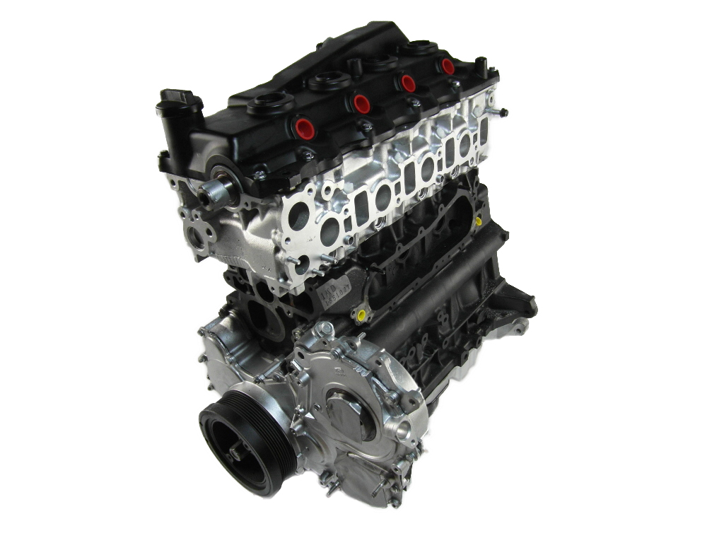
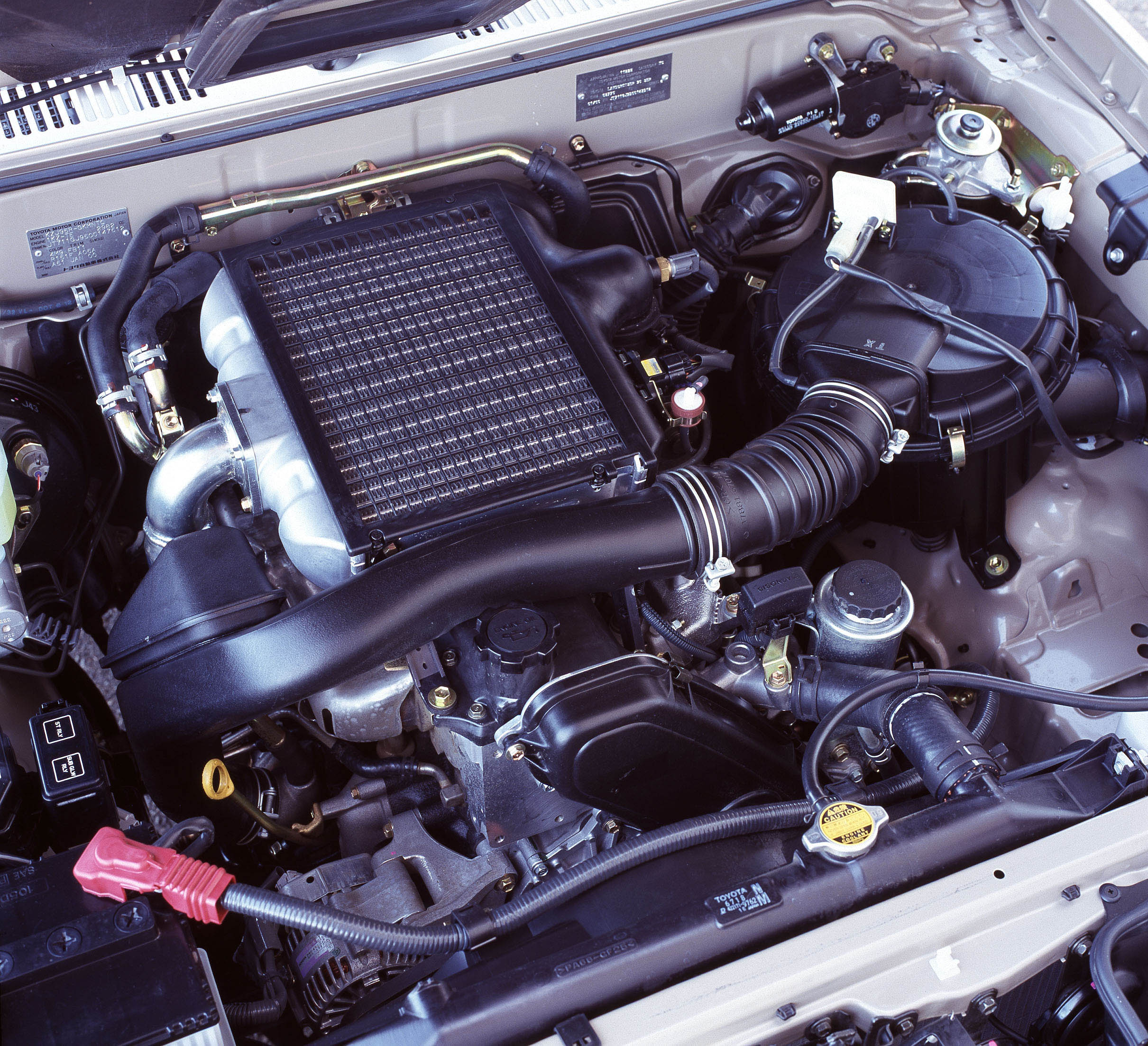
Toyota’s 1HZ was a 4.2-litre diesel engine that was offered in Toyota LandCruiser vehicles . Key features of the 1HZ engine included its cast iron cylinder block and head, single overhead camshaft, two valves per cylinder and indirect injection. Although there are aftermarket examples of turbocharged 1HZ engines, Toyota did not offer a turbocharged 1HZ engine.
In 1998, the 1HZ engine was upgraded for the 105-Series LandCruiser – these changes are included in the description below.
| Engine | Trans. | Years | Peak power | Peak torque | |
|---|---|---|---|---|---|
| Toyota80-Series LandCruiser (HDJ80R) | 4.2-litre diesel I6 | 5sp man. | 1990-98 | 94kW at 4000rpm | 271Nm at 2000rpm |
| Toyota100-Series LandCruiser (HZJ105) | 4.2-litre diesel I6 | 5sp man., 4sp auto |
1998-07 | 96kW at 3800rpm | 285Nm at 2200rpm |
1HZ block
The 4164 cc cast iron cylinder block for the 1HZ had 94.0 mm bores and a 100.00 mm stroke. The cylinder block contained a water jacket through which coolant was pumped to cool the cylinders, while the oil pan was bolted onto the bottom of the crankshaft bearing cap.
For the post-1998 1HZ engine, the rigidity of the cylinder block was improved to reduce noise and vibration.
Crankshaft
The crankshaft for the 1HZ engine had twelve balancing weights and was supported by seven aluminium alloy bearings. The crankshaft bearing cap had ladder frame construction and was incorporated into the crankcase, while plastic region tightening bolts were used for both the crankshaft bearing cap bolts and connecting rod cap bolts. Furthermore, the crankshaft had built-in oil holes to supply oil to the connecting rods, bearings and other components.
For the post-1998 1HZ engine, a more rigid crankshaft was adopted and the crankshaft bearings were machine-bored for greater reliability.
Pistons
The 1HZ engine had aluminium alloy pistons with full-floating type piston pins for which snap rings were fitted to both ends of the pin to prevent the pin from slipping out. Of the piston rings,
- The no.1 compression ring was made of steel
- The no.2 compression ring of cast ring; and,
- The oil ring was made of steel.
The outer diameter of each piston ring was slightly larger than the diameter of the piston and the flexibility of the rings enabled them to hug the cylinder walls when they were mounted on the piston. The no.1 and no.2 compression rings operated to prevent the leakage of gas from the cylinder, while the oil ring scraped oil off the cylinder walls to prevent it from entering the combustion chamber.
From 1998, the top piston ring groove was treated with MMC (Metal Matrix Composites) – previously FRM (Fibre Reinforced Metal) – to increase wear resistance. Furthermore,
- The shape of the piston skirt was optimised and the steel strut discontinued; and,
- The shape of the combustion chamber at the top of the piston was changed.
Cylinder head
The 1HZ engine had a cast iron cylinder head with a cross-flow configuration and swirl-type combustion chamber; plastic region tightening bolts were used for the cylinder head bolts. The camshaft journal part of the cylinder head was made of cast iron and had aluminium alloy camshaft caps.
Camshaft
The 1HZ engine had a single overhead camshaft (SOHC) that was driven by the timing belt. While the original 1HZ engine had an automatic, wear-reducing timing belt tensioner, this was changed to a hydraulic type for the post-1998 1HZ engine. For the post-1998 1HZ engine, a cover with integrated foam rubber was adopted for the timing belt cover gasket for easier servicing.
The camshaft journal was supported at seven locations; lubrication of the camshaft journal and cam occurred via the oil port of the no.7 camshaft journal. With the exception of the no.1 journal, the camshaft journal had no bearings.
Valves
The 1HZ engine had two valves per cylinder – one intake and one exhaust – that were fitted with irregular pitch springs. The valves were actuated directly and valve clearance was adjustment occurred via an outer shim type system in which valve adjusting shims were located above the valve lifters – this enabled the shims to be replaced without having to remove the camshaft.
Valve timing for the 1HZ engine is given in the table below; the 1HZ engine had valve overlap of 13 degrees, intake duration of 224 degrees and exhaust duration of 236 degrees.
| 1HZ Valve Timing | ||
|---|---|---|
| Intake | Open | 8° BTDC |
| Close | 36° ABDC | |
| Exhaust | Open | 51° BBDC |
| Close | 5° ATDC | |
Injection
The 1HZ engine had indirect injection. For the post-1998 1HZ engine, the orifice of the injection nozzle was increased from 1.0 mm to 1.2 mm and its shape was changed to optimise the injection rate. Furthermore, the injection pump adopted Fuel Cut Valve Control (FCVC) and an engine immobiliser was introduced. Upon receiving a signal from the transponder key computer, the FCVC turned off the fuel cut valve to prohibit the engine from starting if an invalid ignition key was used to start the engine.
For the post-1998 1HZ engine, new metal glow plugs were introduced which had a temperature control function in the plug itself; the glow plug resistor and sub-relay were also discontinued.
For the post-1998 1HZ engine, the shape of the combustion chamber and the piston were changed to reduce exhaust emissions. While the original 1HZ engine had a compression ratio of 22.7:1, this was lowered to 22.4:1 for the post-1998 1HZ engine.
Exhaust
The 1HZ engine had dual-type exhaust manifolds.
2002: 1HZ update
In October 2002, the 1HZ engine for the HZJ105 LandCruiser was upgraded with: :
- An exhaust gas recirculation system; and,
- A timing control valve for the fuel injection pump to reduce nitrogen emissions.


